Partial Discharge Online Monitoring System of Generators
Generally, partial discharge occurs at a position where the properties of the dielectric material are not uniform. At these locations, the local electric field strength is enhanced, and local electric field strength is too large, resulting in local breakdown. This partial breakdown is not the total breakdown of the insulating structure. Partial discharges typically require a certain amount of gas space to develop, such as gas voids inside the insulation, adjacent conductors, or insulating interfaces.
When the local field strength exceeds the dielectric strength of the insulating material, a partial discharge occurs, causing many partial discharge pulses to occur during one cycle of applying the voltage.
The amount of discharge delivered is closely related to the non-uniform characteristics and the specific dielectric properties of the material.
Significant partial discharges in the motor are often a sign of insulation defects, such as manufacturing quality or post-run degradation, but this is not a direct cause of failure. However, partial discharges in the motor can also directly damage the insulation and affect the aging process.
Specific partial discharge measurements and analysis can be effectively used for quality control of new windings and winding components as well as early detection of insulation defects caused by factors such as thermal, electrical, environmental and mechanical stresses in operation, which can lead to insulation failures.
Due to specific production techniques, manufacturing defects, normal running aging or abnormal aging,partial discharge may affect the insulation structure of the entire stator winding. The design of the motor, the characteristics of the insulating materials, the manufacturing methods, and the operating conditions greatly affect the number, location, nature, and development trend of the partial discharge. In most cases, through the characteristics of partial discharge, different local discharge sources can be identified and distinguished. Through the development trend and related parameters, to judge system insulation status, and provide anearlier basis for maintenance.
Characterization parameter of partial discharge?
1. Apparent discharge charge q(pc). qa=Cb/(Cb+Cc), the discharge amount is generally expressed by the recurring apparent discharge charge qa.?
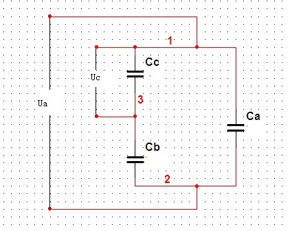
Including Cc is Defect equivalent capacitance
2. Discharge phase φ (degrees)
3. Discharge repetition rate
Software platform
PD collector
Partial discharge sensor 6pcs
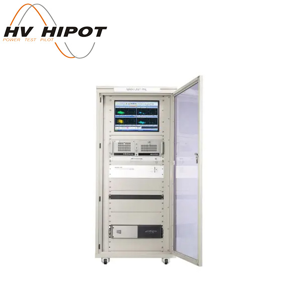
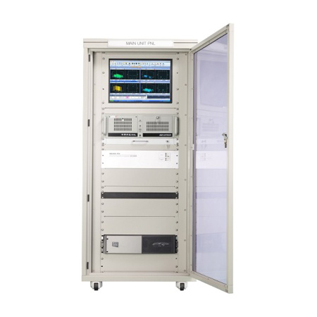
Control cabinet(to put industrial computer and monitor, suggest provided by buyer)
1. Partial discharge signal sensor?
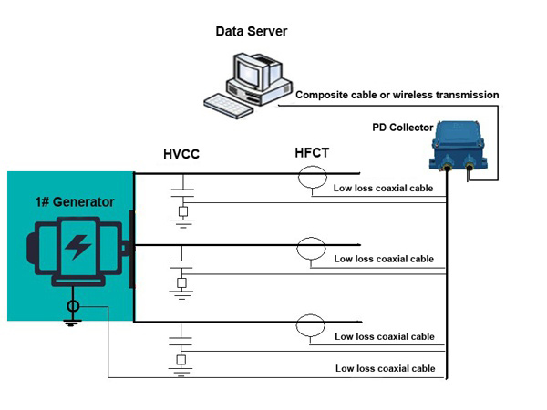
The HFCT partial discharge sensor consists of a magnetic core, a Rogowski coil, a filtering and sampling unit, and an electromagnetic shielding box. The coil is wound on a magnetic core with a high magnetic permeability at high frequency; The design of the filtering and sampling unit considers the requirements of measurement sensitivity and signal response frequency band. In order to suppress interference, improve the signal-to-noise ratio, and consider the requirements of rainproof and dustproof, Rogowski coils and filter sampling units are installed in the metal shielding box. The shield case is designed with a self-locking buckle that can be opened by pressing to maximize ensure the convenience of sensor installation and safety during operation. The HFCT sensor is used to measure the insulation of the PD in the stator windings.
The epoxy mica HV coupling capacitor has a capacity of 80 PF. Measuring coupling capacitors should have high stability and insulation stability, especially pulse overvoltage. PD sensors and other sensors can be connected to the PD receiver. A wide bandwidth HFCT is also called "RFCT" for noise suppression. Typically, these sensors are mounted on a grounded power cable.?

A signal conditioning module is built in the PD sensors. The module mainly amplifies, filters, and detects the signal coupled to the sensor, so that the high-frequency pulse signal can be effectively collected by the data acquisition module.
The specifications of HFCT
|
Frequency range |
0.3MHz ~ 200MHz |
|
Transfer impedance |
Input 1mA, Output ≥15mV |
|
Working temperature |
-45℃?~ +80℃ |
|
Storage temperature |
-55℃?~ +90℃ |
|
Hole diameter |
φ54(customized) |
|
Output terminal |
N-50 socket |
?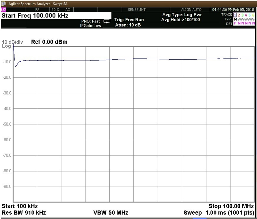
Amplitude-frequency characteristic of HFCT
2. PD online detection unit (PD collector)
The partial discharge detection unit is the most important component of the system. Its functions include data acquisition, data storage and processing, and be able to drive the optical fiber LAN or transmit data through WIFI and 4G wireless communication methods. The partial discharge signal and grounding current signal of multiple sets of joints (ie ABC three-phase) can be installed in the terminal cabinet near the measuring point or in the self-supporting outdoor terminal box. Due to the harsh environment, a waterproof box is required. The outer casing of the testing device is made of stainless steel, which is good for shielding high frequency and power frequency. Since it is outdoor installation, it should be mounted on the waterproof cabinet, the waterproof rating is IP68, and the operating temperature range is -45°C to 75°C.
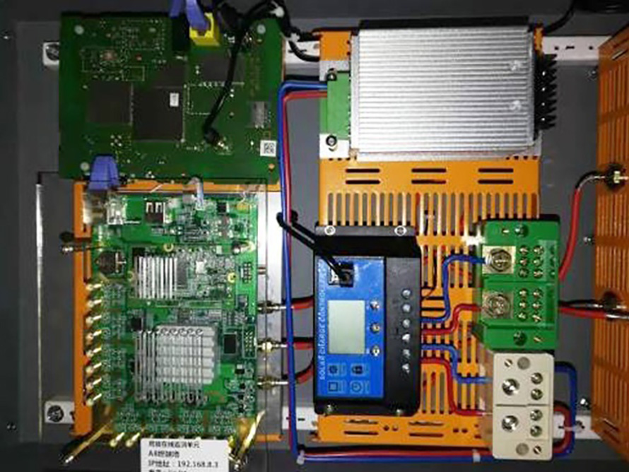
Internal structure of online detecting unit
Parameters and functions of online detecting unit
It can detect basic partial discharge parameters such as discharge amount, discharge phase, discharge number, etc., and can provide statistics on relevant parameters according to customer requirements.
The sampling rate of the partial discharge pulse signal is not less than 100 MS/s.
Minimum measured discharge: 5pC; measurement band: 500kHz-30MHz; discharge pulse resolution: 10μs; phase resolution: 0.18°.
It can display the power frequency cycle discharge diagram, two-dimensional (Q-φ, N-φ, N-Q) and three-dimensional (N-Q-φ) discharge spectra.
It can record relevant parameters such as measuring phase sequence, discharge amount, discharge phase and measurement time. It can provide discharge trend graph and has pre-warning and alarm functions. It can query, delete, backup and print reports on the database.
The system includes the following contents for signal acquisition and processing: signal acquisition and transmission, signal feature extraction, pattern recognition, fault diagnosis and cable equipment status assessment.
The system can provide the phase and amplitude information of the PD signal and the density information of the discharge pulse, which is helpful to judge the type and severity of the discharge.
Communication mode selection: support network cable, fiber optic, wifi self-organizing LAN.
3. PD software system
The system uses configuration software as a development platform for acquisition and analysis software to ensure good implementation of anti-interference technology. System software can be divided into parameter setting, data acquisition, anti-interference processing, spectrum analysis, trend analysis, data collation and reporting.
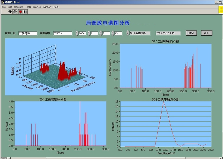
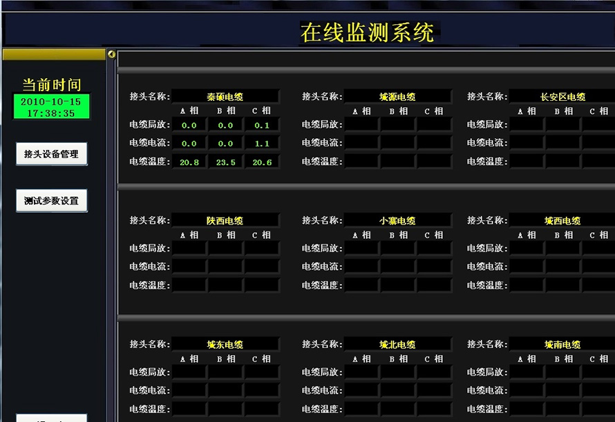
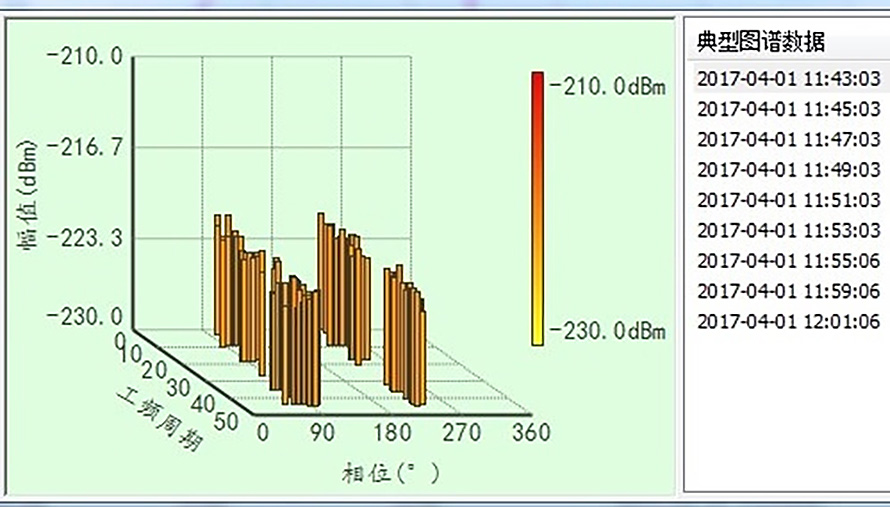
Among them, the data acquisition part mainly completes the setting of the data acquisition card, such as the sampling period, the maximum point of the cycle, and the sampling interval. The acquisition software collects data according to the set acquisition card parameters, and automatically sends the collected data to the anti-interference software for processing. Besides the anti-interference processing part, which is executed in the background of the program, the rest is displayed through the interface.
Software system features
The main interface dynamically prompts important monitoring information and clicks the corresponding prompt to directly obtain detailed information.
The operation interface is convenient to use and improve the efficiency of information acquisition.
With powerful database search function for form query, trend graph and Pre-warning analysis, spectrum analysis, etc.
With online data collection function, which can scan the data of each subsystem in the station at the time interval set by the user.
With equipment fault warning function, when the measured value of the online detection item exceeds the alarm limit, the system will send an alarm message to remind the operator to handle the equipment accordingly.
The system has a complete operation and maintenance function, which can conveniently maintain system data, system parameters, and operation logs.
The system has strong scalability, which can easily realize the addition of state detection items of various devices, and adapt to the expansion of business volume and business processes;With log management function, which records user operation logs and system communication management logs in detail, which can be easily queried or self-maintained.
4. Control cabinet?
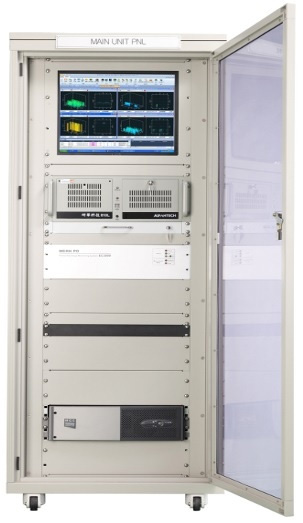
The control cabinet put monitor and industrial computer, or other necessary accessories. It is better to be supplied by use?
The cabinet is fixedly installed in the main control room of the substation, and other locations can be selected for installation according to site requirements.?
?
1. Functions
The HFCT sensor is used to measure the insulation of the PD in the stator windings. The epoxy mica HV coupling capacitor is 80pF. Measuring coupling capacitors should have high stability and insulation stability, especially pulse overvoltage. PD sensors and other sensors can be connected to the PD collector. Wideband HFCT is used for noise suppression. Typically, these sensors are mounted on a grounded power cable.
The most difficult aspect of PD measurement is noise suppression in high voltage equipment, especially HF pulse measurement because it has a lot of noise. The most effective noise suppression method is the "arrival time" method, which is based on detecting and analyzing the difference in pulse arrival times of several sensors from one PD to the monitoring system. The sensor will be placed close to the insulated discharge position through which the early high frequency pulses of the discharge are measured. The position of the insulation defect can be detected by the difference in pulse arrival time.
Specifications of PD collector
● PD channel: 6-16.
● Pulse frequency range (MHz): 0.5~15.0.
● PD pulse amplitude (pc) 10~100,000.
● Built-in expert system PD-Expert.
● Interface:Ethernet, RS-485.
● Power supply voltage: 100~240 VAC, 50 / 60Hz.
● Size (mm): 220*180*70.
● With strong anti-interference ability. The system uses broadband detection technology and has a complete interface protection circuit to effectively resist large current surges and low power consumption.
● With recording function, save the original test data, and the original data when the test state can be played back.
● According to the field conditions, the optical fiber LAN transmission network can be used, and the transmission distance is long, stable and reliable. The structure is compact, easy to install, and can also be realized by a fiber-optic LAN structure.
● The configuration software is used to facilitate the on-site configuration interface.
2. Applied Standard
● IEC 61969-2-1:2000 Mechanical structures for electronic equipment Outdoor enclosures Part 2-1.
● IEC 60270-2000 Partial Discharge Measurement.
● GB/T 19862-2005 Industrial automation instrumentation insulation resistance, insulation strength technical requirements and test methods.
● IEC60060-1 High voltage test technology Part 1: General definitions and test requirements.
● IEC60060-2 High voltage test technology Part 2: Measurement systems.
● GB 4943-1995 Safety of information technology equipment (including electrical affairs equipment).
● GB/T 7354-2003 Partial discharge measurement.
● DL/T417-2006 Site Guidelines for Partial Discharge Measurement of Power Equipment.
● GB 50217-2007 Power Engineering Cable Design Specification.
